






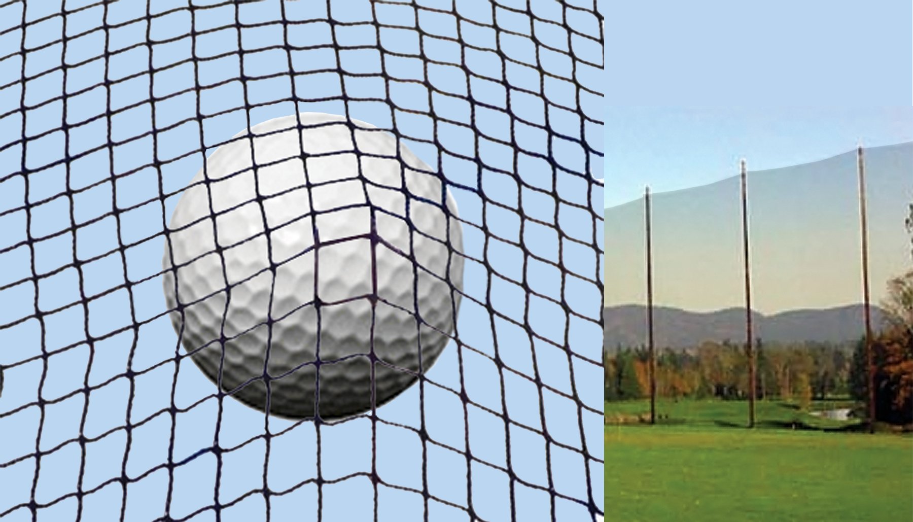

Building a DIY golf simulator enclosure is easier when you know which materials to buy, how to cut the frame poles and what order to assemble the components. A properly planned kit lets you handle the installation while using enclosure components designed to work together.
This guide explains how to prepare your room, choose your frame materials and follow the assembly sequence for America's Golf Mats enclosure kits. You will also find the assembly manuals and pole cutting charts for all 19 current models.
Start with your room measurements, then use the instructions and cutting chart for the exact enclosure you order.
Plan the Room Before Buying Materials
Measure the usable ceiling height, room width and total room depth. Include obstacles such as beams, lights, garage-door tracks, cabinets and doors that need space to open.
Mark the planned ball position and golf-mat location. Allow for the mat's thickness when checking overhead clearance, and carefully test swing clearance with your longest intended club. If both right- and left-handed golfers will use the simulator, check both positions.
Enclosure depth is not the total room depth your simulator needs. You also need space for the hitting position, the golfer's swing, screen movement and your launch monitor's required placement. A 2-foot-deep enclosure does not mean you can build a complete simulator in a 2-foot-deep room.
Use your launch monitor's installation requirements and your projector's throw-distance specifications before finalizing the layout. Keep the impact screen clear of hard surfaces behind it according to the selected enclosure's instructions. An enclosure designed to sit against a wall can still position its screen farther forward inside the frame.
Choose Your Enclosure and Open the Correct Instructions
America's Golf Mats offers four enclosure series with different frame layouts and installation requirements. Use the matching manual throughout the build; hardware positions and screen attachment methods are not interchangeable.
| Enclosure series | Current models | Enclosure depth | Assembly instructions | Chart for locally purchased frame materials |
|---|---|---|---|---|
| America's Compact™ | 5 | 2 feet | Compact assembly manual | Pole cutting chart — PDF page 4 |
| America's Choice™ | 4 | 5 feet | Choice assembly manual | Pole cutting chart — PDF page 5 |
| America's SafetyMax™ | 4 | 6 feet | SafetyMax assembly manual | Pole cutting chart — PDF page 9 |
| America's Wall-to-Wall Studio Series™ | 6 | 5 or 8 feet | Wall-to-Wall assembly manual | EMT and Unistrut cutting charts — PDF page 4 |
Choose the row in the cutting chart that matches your ordered height, width and depth. The manuals may also show additional configurations; check the product page for the sizes currently available.
Still deciding which enclosure suits your room? Read the Golf Simulator Enclosure Comparison & Selection Guide, or shop golf simulator enclosure kits.
Choose Local Frame Materials or a Pre-Cut Pole Kit
Our enclosure kits include a premium impact screen. Frame poles are sold separately; projectors are not included, and golf mats are sold separately. Check your selected model's included components and optional upgrades before ordering.
For locally sourced poles, purchase 1-inch trade-size EMT conduit from Home Depot, Lowe's or your local hardware store. Its actual outside diameter is approximately 1 3/16 inches. Match the material specified in your manual rather than choosing tubing by an estimated diameter.
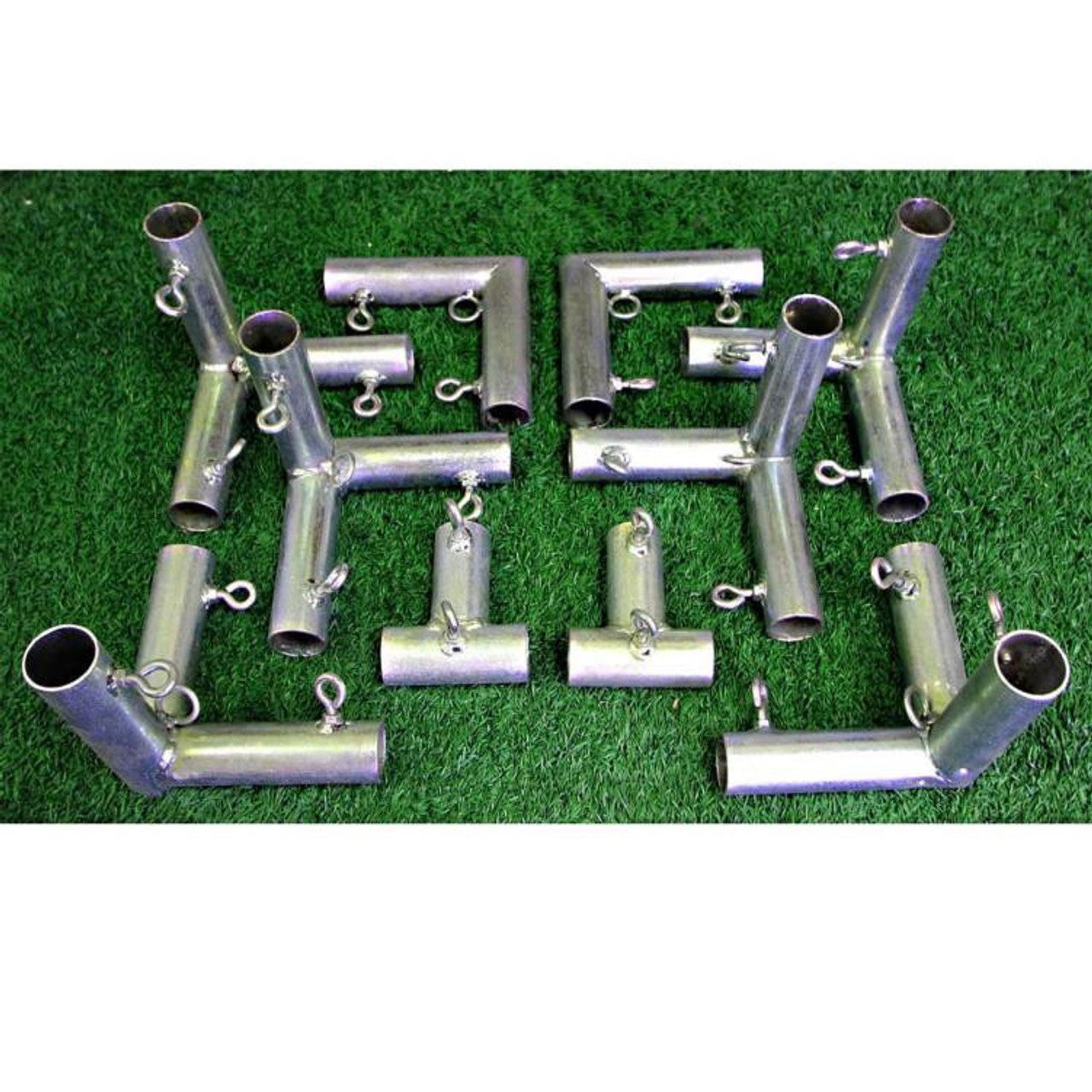
The cutting chart gives the quantity of stock poles and the finished lengths required. Do not cut poles to the advertised enclosure dimensions. The connectors contribute to the assembled size, so the pole lengths are different.
Alternatively, choose the available pre-cut pole kit for your model. Compare its parts with the manual's pole-kit chart before assembly. The pre-cut-kit verification chart and the local-pole cutting chart serve different purposes.
For Wall-to-Wall Studio Series installations, also check the shallow steel channel strut, commonly called Unistrut or SuperStrut, specified in the manual. Its page 4 provides separate EMT and strut charts. Confirm the steel channel components supplied with your selected frame option before purchasing additional materials.
Gather Your Tools and Organize the Parts
Prepare these tools as needed for your model and frame option:
- Tape measure and pencil or marker.
- Wrenches for the frame hardware and cable fittings.
- Screwdriver where required by the supplied hardware.
- Step ladder for overhead components.
- Scissors or a utility knife for trimming attachment materials.
- Tubing cutter or hacksaw if cutting EMT locally; suitable cutting equipment for any required steel channel strut.
- Gloves and wire cutters for models with cable assemblies.
Use eye protection when cutting metal and remove sharp burrs before assembly. Have a second adult help with raising the frame and installing overhead components.
Lay out the connectors, fabric panels, screen and attachment hardware. Separate height, width and depth poles, then label cut pieces so similar lengths do not get mixed up. Check everything against the manual's parts list before starting.
Assemble Your Enclosure in the Correct Order
The following sequences explain the main stages. Keep your model's illustrated manual open for connector orientation, insertion depths, cable attachment and individual hardware details.
America's Compact™ Assembly Sequence
- Build the frame: assemble the bottom, rear, upper depth poles and front sections in the order shown for your local poles or pre-cut kit.
- Confirm the assembled dimensions: measure the outer height, width and depth before adding fabric.
- Prepare the covering and screen supports: install the optional rear panel if purchased, apply the specified hook-and-loop strips and add the lower pole sleeves.
- Install the screen-tension cables: assemble and position the cables and turnbuckles as illustrated.
- Hang the impact screen: attach it loosely first, level it and adjust the sides evenly. Smooth the screen without making it overly tight.
- Add the side and top panels: align the panels before tightening the attachments. If purchased, install the FoamDefender safety valance before the SkyGuard netting, as directed in the manual.
America's Choice™ Assembly Sequence
- Build the frame: assemble the bottom, rear, upper depth and front sections using the diagram for your frame option.
- Confirm the assembled dimensions before fitting the fabric.
- Fit the upper pole sleeves and wrapper: position the wrapper with its grommets at the rear, then follow the manual's wrapping and bungee sequence.
- Install the screen: face the screen logo toward the golfer, start with the corners, attach the top and bottom, then attach the sides. Follow the illustrated bungee orientation.
- Finish the enclosure: install the optional baffle net and any ordered foam inserts and trim as directed.
America's SafetyMax™ Assembly Sequence
- Build the frame with its screen-support section: follow the SafetyMax connector layout rather than the Choice layout.
- Confirm the outer dimensions and screen-support position against the manual.
- Install the upper pole sleeves and wrapper: follow the wrapping sequence and attach it to the indicated frame sections.
- Hang the screen on the designated middle frame section: orient the logo toward the golfer and attach the corners, top, bottom and sides as illustrated.
- Install the baffle net directly behind the screen, then close and secure the rear wrapper flaps.
- Fit the protective foam and trim: complete the side and top protection before using the enclosure. Install any optional containment accessories according to their instructions.
America's Wall-to-Wall Studio Series™ Assembly Sequence
- Prepare the EMT and steel channel strut using the correct charts for your size and depth.
- Build the frame: follow the rear, bottom and depth-pole sequence, then add the intermediate and front uprights.
- Install the SkyBridge brackets and width struts, along with the required center support shown for your configuration.
- Verify the complete frame dimensions before adding the covering.
- Install the pipe sleeves, top netting and blackout panels in the manual's order, including the optional rear panel if purchased.
- Assemble the side-shade and side-netting cables, then hang the baffle net and impact screen as illustrated.
- Complete the protective components: install the overhead valance, angled side shades and side netting. Follow the specified attachment points and tension settings.
This installation has additional structural and cable components. Read the entire manual before beginning so you understand where the screen, struts and angled interior panels will sit.
Set Up the Screen, Golf Mat and Projector
An impact screen needs room to respond to a ball strike. Do not pull it drum-tight or position it where it can strike a hard surface behind it. Use the attachment method and screen position specified for your enclosure.
Screen Size vs. Viewable White Area
Our impact screens have a 2-inch black border on all four sides. The viewable white projection area is therefore 4 inches narrower and 4 inches shorter than the overall screen dimensions.
When planning your projected image, use the viewable white-screen dimensions rather than the overall screen or enclosure dimensions. Check the selected model's screen specifications to match your projector and desired 4:3 or 16:9 image to the available white area.

Place your golf mat at the hitting position you planned, then confirm swing clearance and launch-monitor alignment again. America's Golf Mats offers ProStrike Zero Shock™ golf simulator mats for customers building an indoor hitting area.
Position the projector using its specified throw distance and mounting instructions. Check that the image fits the white projection area and that the golfer, frame and overhead components do not obstruct the projected image.
Check the Finished Installation Before Hitting
Before use, check that:
- Frame dimensions match your ordered enclosure and all connections are secured as instructed.
- The screen faces the correct direction and has the required clearance to move.
- Fabric, baffle netting, foam and any purchased containment accessories are fully installed.
- Exposed hard components and gaps around the hitting area have been addressed according to the manual.
- Your mat and launch monitor are correctly positioned and your swing clears nearby obstacles.
- Other people and pets remain outside the swing area and potential ball path.
Begin with a controlled check using lightweight practice balls and inspect the installation before progressing. Follow the manual's safety precautions throughout use. No enclosure removes every risk from an indoor golf shot; containment needs depend on your layout, hitting position and the golfers using it.
Need Help Choosing Your DIY Enclosure?
Have your usable room height, width and depth ready, along with your launch monitor model and planned hitting position. These details help us recommend an enclosure and frame option that fit your project.
Shop Golf Simulator Enclosure Kits or use the Ask SARA form below for help planning your installation.
Explore the Golf Simulator Enclosure Learning Center.
Ask SARA
America's Golf Simulator Enclosure Expert™
A successful DIY golf simulator enclosure starts with understanding the room before buying materials or choosing the enclosure.
Reviewed by David Quail — America's Golf Mats
Golf products industry experience since 1997.
Golf simulator enclosure manufacturing experience dating to 2010.
Meet David Quail - Golf Simulator Enclosure Expert →


